What is a series and parallel circuit? How are they different from one another, and can you use them in combination?
Circuits with just one load resistance and one battery can be analyzed quite simply, but are not usually found in practice.
More commonly, you will see circuits where two or more components are connected together. These will be connected in either a series or parallel circuit.
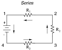
A series circuit:
In this example there are three resistors (R1, R2, and R3 – the numbers are for identification only and do not represent the value in ohms).
They are connected from one battery terminal to the other. The main characteristic defining a series circuit is that the electrons can only flow in one direction, along just one path.
This circuit shows the electrons flowing counter-clockwise, from point 4 through to 1 and back around to 4.
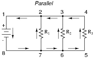
A parallel circuit:
There are still three resistors in this example, but this time the electrons have more than one path where they can flow continuously. The one from 8 to 7 to 2 to 1 and back to 8.
One from 8 to 7 to 6 to 3 to 2 to 1 and back to 8. And the one from 8 to 7 to 6 to 5 to 4 to 3 to 2 to 1 and back to 8. Each of the paths (through R1, R2, and R3) are called branches.
A parallel circuit is when all components are connected in between common electrical points. Note that points 1, 2, 3, and 4 are all electrically common. As are points 8, 7, 6, and 5. The battery and all of the resistors are connected between these points.
In many cases you will see a combination series and parallel circuit:
This example combination series and parallel circuit shows two loops where the electrons travel – one from 6 to 5 to 2 to 1 and back to 6, and the other from 6 to 5 to 4 to 3 to 2 to 1 and back to 6.
Note how the path of both currents pass through R1 (from point 2 to point 1). This means that R2 and R3 form a parallel, while R1 forms a series with the R2-R3 parallel combination.


No comments:
Post a Comment