What is Electrical Engineering,Electrical engineering Projects,Electrical Energy and Transformers and all Electrical related articles daily updates in this blog.
If we are
going to recall our Physics subject, it is said that whenever a force
is applied that causes motion the work is said to be done. Take a look
on the illustration below:
Forces that work is done and forces not doing work.
The
first figure shown above are combination of forces which work is done
and forces which work is not done. (a)The picture in which the shelf is
held under tension does not cause motion, thus work is not done. (b)
The second picture in which the woman pushes the cart causes motion,
thus the work is done. (c) The man applied tension in the string is not
working since as there is no movement in the direction of the force.
(d) The track applied horizontal force on the log is doing work.
The potential difference between any two points in an electric circuit, which gives rise to a voltage and when connected causes electron to move and current to flow. This is one of a good example in which forces causing motion, thus causing work to be done.
Talking about work in electric circuit, there is also a electric power which is the time rate of doing work done of moving electrons from point to point. It is represented by the symbol P, and the unit of power is watt, which is usually represented by the symbol W. Watt
is practically defined as the rate at which work is being done in a
circuit in which the current of 1 ampere is flowing when the voltage
applied is 1 volt.
The Useful Power Formula
Electric Power can be transmitted
from place to place and can be converted into other forms of energy.
One typical energy conversion of electrical energy are heat, light or
mechanical energy. Energy conversion is what the engineers really mean
for the word power.
The power or the rate of work done
in moving electrons through a resistor in electric circuit depends on
how many electrons are there to moved. It only means that, the power consumed in a resistor is determined by the voltage measured across it, multiplied by the current flowing through it. Then it becomes,
Power = Voltage x Current
Watts = Volts x Amperes
P = E x I or P = EI ------> formula no.1
The power formula above can be
derived alternatively in other ways in terms of resistance and current
or voltage and resistance using our concept of Ohm's Law.
Since E=IR in Ohm's Law, the E in the power formula above can be
replaced by IR if the voltage is unknown. Therefore, it would be:
P = EI
P = (IR)I or P = I2R------------> formula no.2
Alternatively if I = E/R in
Ohm'Law, we can also substitute it to E in the power formula which is
terms of voltage if the resistance is unknown.
P = EI
P = E(E/R) or P = E2R ---------> formula no. 3
For guidance regarding expressing of units of power are the following:
a. Quantities of power greater than 1,000 watts are generally expressed in (kW).
b. Quantities greater than 1,000,000 watts are generally expressed as megawatts (MW).
c. Quantities less than 1 watt are generally expressed in (mW).
The Power Rating of Equipment
Most of the electrical equipment
are rated in terms of voltage and power - volts and watts. For example,
electrical lamps rated as 120 volts which are for use in 120 volts line
are also expressed in watts but mostly expressed in watts rather than
voltage. Probably you would wonder what wattage rating all about.
The wattage rating of an
electrical lamps or other electrical equipment indicates the rate at
which electrical energy is changed into another form of energy, such as
heat or light. It only means the greater the wattage of an
electrical lamp for example, the faster the lamp changes electrical
energy to light and the brighter the lamp will be.
The principle above also applies to
other electrical equipment like electric soldering irons, electrical
motors and resistors in which their wattage ratings are designed to
change electrical energy into some forms of energy. You will learn more
about other units like horsepower used for motors when we study motors.
Take a look at the sizes of carbon resistors
below. Their sizes are depends on their wattage rating. They are
available with same resistance value with different wattage value. When
power is used in a material having resistance, electrical energy is
changed into heat. When more power are used, the rate at which
electrical energy changed into heat increases, thus temperature of the
material rises. If the temperature of the material rises too high, the
material may change it composition: expand, contract or even burn. In
connection to this reason, all types of electrical equipment are rated
for a maximum wattage.
Carbon resistors with comparative sizes of different wattage ratings of 1/4 watt, 1/2 watt,1 and 2 watts
If the resistors greater then 2 watts rating are needed, wire-wound resistors are used. They are ranges between 5 and 200 watts, with special types being used for power in excess of 200 watts.
Use wire wound resistors if higher than 2 watts are needed
Fuses
We all know that when current passes through the resistors, the electrical energy is transformed into heat which raises the temperature of the resistors. If
the temperature rises too high, the resistor may be damaged thereby
opening the circuit and interrupting the current flow. One answer for
this is to install the fuse.
Fuses are resistors using special metals with very low resistance value and a low melting point. When the power
consumed by the fuses raises the temperature of the metal too high, the
metal melts and the fuse blows thus open the circuit when the current
exceeds the fuse's rated value. What is the identification of blown
fuse? Take a look on the picture below.
This is the good fuse
This is the blown fuse
In
other words, blown fuses can be identified by broken filament and
darkened glass. You can also check it by removing the fuse and using
the ohmmeter.
There are two types of fuses in use today - conventional fuses, which blow immediately when the circuit is overloaded. The slow-blowing
(slo-blo) fuses accepts momentary overloads without blowing, but if the
overload continues, it will open the circuit. This slo-blo fuses
usually used on motors and other appliances with a circuit that have a
sudden rush of high currents when turned on.
Fuses are rated in terms of
current. Since various types of equipments use different currents,
fuses are also made with different sizes, shapes and current ratings.
Various types of fuses are made for various equipments
Proper
rating of fuse is needed and very important. It should be slightly
higher than the greatest current you expect in the circuit because too
low current rating of fuse will result to unnecessary blowouts while
too high may result to dangerously high current to pass.
Later we will be study circuit breaker which is another protective devices for over current protection.
Electrical Power in Series, Parallel and Complex Circuits
The principle of getting the total power of the circuit is just simple. There is no need to elaborate this topic.
The total power consumed by the circuit is the sum of all power consumed in each resistance.
Therefore, we just only sum up all power consumed in each resistance whether it a series, parallel or a complex circuits. Thus,
Pt= P1+P2+P3+Pnwatts ---------->formula no. 4
From the problem in my previous post about complex circuit, try to calculate each power of the resistance and the total power as well. Constant practice always makes you perfect!
One of the many
electrical engineering careers includes working with digital
technology. This career allows electrical engineers to work with
digital technology and to develop ways to make digital technology small
enough to be easy to use. Workers in this career may be able to work
with cell phone companies to make the required technology small enough
to fit into the smallest cell phone or they may design technology to
make cell phones more efficient. This can be an exciting career for an
electrical engineer and can be quite lucrative as well.
Electrical
engineering is another rewarding type of engineering that is available
for individuals today. Just like computer hardware engineering, an
electrical engineer is instrumental in every aspect of building any
electrical product. The electrical engineer is closely related to every
part of the building cycle of any electric product. The electrical
engineer is also instrumental in building, installing, repairing and
servicing any of the electrical instruments. Therefore, it can be said
that the electrical engineer is the backbone of any electrical
engineering product.
Usually,
electrical engineering jobs require that engineers work with electrical
systems on quite a large scale, but one branch, electronic engineering,
deals with the electrical systems on a very small scale. Usually, these
types of electrical engineering jobs require dealing with small
integrated circuits and computer systems. Whether an electrical
engineer deals with small electrical systems or large electrical
systems, there are a variety of electrical engineering jobs available.
How to become an electrical engineer?
If
you want to embrace a career as an electrical engineer, you are
generally required to graduate from college in engineering. Just like
any other engineering career, you will need to have excellent grade in
mathematics and science to study in an engineering schools. Being a
science-oriented student is not enough, you will be required to have
good skills in English, social studies, and computers. Most recruiters
also expect their engineers to be creative, curious, logical,
detail-oriented and good team-workers.
It
is essential for an engineer to effectively communicate their ideas and
suggestions to others in their field. A successful Electrical Engineer
is a person who has perfect understanding and knowledge about his field
and also possesses good grasp of principles of engineering in general
as well. That's why you are going to study fundamentals of engineering
in beginning. After getting perfect mastery over fundamentals, you can
now start focusing on your area of expertise.
Large
personal gains and contributions to the community make electric
engineering a very useful major that a young person could study.
Electric engineers have already contributed to many sectors of life,
including the applications in the aerospace industry and the military.
Such influence will only enlarge as technology advances and becomes an
important factor in our daily life. As electric engineers' influences
grow, the importance of electric engineering also becomes more
significant.
The field then subdivides into eight primary areas:
Power, control, electronics, microelectronics, signal, telecommunications,instrumentation
and, probably the fastest growing of the areas, computers. There are
many who practice more than one of these sub-disciplines, but it's
possible to specialize in just one of them and make quite a career out
of it. There's also one very popular cross discipline called
mechatronics that combines mechanical and electronic engineering.
Digital and analog
electronics is another form of electrical engineering technology that
engineers must be well acquainted with to perform their jobs. Both
digital and analog electronics are used in computers and phones,
however, digital electronics are becoming more widely used as analog
electronics is becoming more and more outdated. This form of electrical
engineering technology requires that engineers understand Boolean
algebra, digital circuits, and how logic gates work. Even those that
deal with digital electronics must also understand the electrical
engineering technology of analog electronics as well. Digital
electronics are usually built with various analog components, so
understanding how analog electronics work is essential.
You should
understand that electrical engineers is not the same as electronic
engineers. While the two may sound the same, there are great
differences between the two. An electrical engineer will deal with
electricity and electrical things on a large scale, where electronic
engineers will deal with smaller electronics such as cell phones and
computers and the components that are inside them.
Electrical engineering is a field of engineering that generally deals with the study and application of electricity, electronics and electromagnetism. The field first became an identifiable occupation in the late nineteenth century after commercialization of the electric telegraph and electrical power supply. It now covers a range of subtopics including power, electronics, control systems, signal processing and telecommunications.
Electrical engineering may or may not include electronic engineering.
Where a distinction is made, usually outside of the United States,
electrical engineering is considered to deal with the problems
associated with large-scale electrical systems such as power transmission and motor control, whereas electronic engineering deals with the study of small-scale electronic systems including computers and integrated circuits.
Alternatively, electrical engineers are usually concerned with using
electricity to transmit energy, while electronic engineers are
concerned with using electricity to transmit information. More
recently, the distinction has become blurred by the growth of power
electronics.
POWER SYSTEM
Power engineering, also called power systems engineering, is a subfield of engineering that deals with the generation, transmission and distribution of electric power as well as the electrical devices connected to such systems including generators, motors and transformers. Although much of the field is concerned with the problems of three-phase AC power
- the standard for large-scale power transmission and distribution
across the modern world - a significant fraction of the field is
concerned with the conversion between AC and DC power as well as the development of specialized power systems such as those used in aircraft or for electric railway networks.
BASICS OF ELECTRIC POWER
Electric power is the mathematical product of two quantities: current and voltage. These two quantities can vary with respect to time (AC power) or can be kept at constant levels (DC power).
Most
refrigerators, air conditioners, pumps and industrial machinery use AC
power whereas most computers and digital equipment use DC power (the
digital devices you plug into the mains typically have an internal or
external power adapter to convert from AC to DC power). AC power has
the advantage of being easy to transform between voltages and is able
to be generated and utilized by brushless machinery. DC power remains
the only practical choice in digital systems and can be more economical
to transmit over long distances at very high voltages.
The
ability to easily transform the voltage of AC power is important for
two reasons: Firstly, power can be transmitted over long distances with
less loss at higher voltages. So in power networks where generation is
distant from the load, it is desirable to step-up the voltage of power
at the generation point and then step-down the voltage near the load.
Secondly, it is often more economical to install turbines that produce
higher voltages than would be used by most appliances, so the ability
to easily transform voltages means this mismatch between voltages can
be easily managed.
Solid state devices, which are products of the semiconductor revolution, make it possible to transform DC power to different voltages, build brushless DC machines and convert between AC and DC power.
Nevertheless, devices utilizing solid state technology are often more
expensive than their traditional counterparts, so AC power remains in
widespread use.
POWER
Power Engineering deals with the generation, transmission and distribution of electricity as well as the design of a range of related devices. These include transformers, electric generators, electric motors and power electronics.
The power grid
is an electrical network that connects a variety of electric generators
to the users of electric power. Users purchase electricity from the
grid avoiding the costly exercise of having to generate their own.
Power engineers may work on the design and maintenance of the power
grid as well as the power systems that connect to it. Such systems are
called on-grid power systems and may supply the grid with additional power, draw power from the grid or do both.
Power engineers may also work on systems that do not connect to the grid. These systems are called off-grid power systems
and may be used in preference to on-grid systems for a variety of
reasons. For example, in remote locations it may be cheaper for a mine
to generate its own power rather than pay for connection to the grid
and in most mobile applications connection to the grid is simply not
practical.
Today, most grids adopt three-phase electric power with alternating current.
This choice can be partly attributed to the ease with which this type
of power can be generated, transformed and used. Often, the power is
split before it reaches residential customers whose low-power
appliances rely upon single-phase electric power.
However, many larger industries and organizations still prefer to
receive the three-phase power directly because it can be used to drive
highly efficient electric motors such as three-phase induction motors.
Transformers play an important role in power transmission because they allow power to be converted to and from higher voltages. This is important because higher voltages suffer less power loss during transmission.
This is because higher voltages allow for lower current to deliver the
same amount of power, as power is the product of the two. Thus, as the
voltage steps up, the current steps down. It is the current flowing through the components that result in both the losses and the subsequent heating.
These losses, appearing in the form of heat, are equal to the current
squared times the electrical resistance through which the current
flows, so as the voltage goes up the losses are dramatically reduced.
For these reasons, electrical substations
exist throughout power grids to convert power to higher voltages before
transmission and to lower voltages suitable for appliances after
transmission.
COMPONENTS
Power
engineering is a network of interconnected components which convert
different forms of energy to electrical energy. Modern power
engineering consists of three main subsystems: the generation
subsystem, the transmission subsystem, and the distribution subsystem.
In the generation subsystem, the power plant produces the electricity.
The transmission subsystem transmits the electricity to the load
centers. The distribution subsystem continues to transmit the power to
the customers.
GENERATION
Generation
of electrical power is a process whereby energy is transformed into an
electrical form. There are several different transformation processes,
among which are chemical, photo-voltaic, and electromechanical.
Electromechanical energy conversion is used in converting energy from coal, petroleum, natural gas, uranium,
water flow, and wind into electrical energy. Of these, all except the
wind energy conversion process take advantage of the synchronous AC
generator coupled to a steam, gas or hydro turbine such that the
turbine converts steam, gas, or water flow into rotational energy, and
the synchronous generator then converts the rotational energy of the
turbine into electrical energy. It is the turbine-generator conversion
process that is by far most economical and consequently most common in
the industry today.
The AC synchronous machine
is the most common technology for generating electrical energy. It is
called synchronous because the composite magnetic field produced by the
three stator
windings rotate at the same speed as the magnetic field produced by the
field winding on the rotor. A simplified circuit model is used to
analyze steady-state
operating conditions for a synchronous machine. The phasor diagram is
an effective tool for visualizing the relationships between internal
voltage, armature current, and terminal voltage. The excitation control
system is used on synchronous machines to regulate terminal voltage,
and the turbine-governor system is used to regulate the speed of the
machine.
The operating costs of generating electrical energy is determined by the fuel cost and the efficiency of the power station.
The efficiency depends on generation level and can be obtained from the
heat rate curve. We may also obtain the incremental cost curve from the
heat rate curve. Economic dispatch is the process of allocating the
required load demand between the available generation units such that
the cost of operation is minimized.
TRANSMISSION
The electricity is transported to load locations from a power station
to a transmission subsystem. Therefore we may think of the transmission
system as providing the medium of transportation for electric energy.
The transmission system may be subdivided into the bulk transmission system and the sub-transmission system.
The functions of the bulk transmission are to interconnect generators,
to interconnect various areas of the network, and to transfer
electrical energy from the generators to the major load centers. This
portion of the system is called "bulk" because it delivers energy only
to so-called bulk loads such as the distribution system of a town,
city, or large industrial plant. The function of the sub-transmission
system is to interconnect the bulk power system with the distribution
system.
Transmission
circuits may be built either underground or overhead. Underground
cables are used predominantly in urban areas where acquisition of
overhead rights of way are costly or not possible. They are also used
for transmission under rivers, lakes and bays. Overhead transmission is
used otherwise because, for a given voltage level, overhead conductors are much less expensive than underground cables.
The
transmission system is a highly integrated system. It is referred to
the substation equipment and transmission lines. The substation
equipment contain the transformers, relays, and circuit breakers. Transformers are important static devices which transfer electrical energy from one circuit with another in the transmission subsystem. Transformers are used to step up the voltage on the transmission line to reduce the power loss which is dissipated on the way. A relay
is functionally a level-detector; they perform a switching action when
the input voltage (or current) meets or exceeds a specific and
adjustable value. A circuit breaker
is an automatically-operated electrical switch designed to protect an
electrical circuit from damage caused by overload or short circuit. A
change in the status of any one component can significantly affect the
operation of the entire system. There are three possible causes for
power flow limitations to a transmission line. These causes are thermal overload, voltage instability, and rotor angle instability.
Thermal overload is caused by excessive current flow in a circuit
causing overheating. Voltage instability is said to occur when the
power required to maintain voltages at or above acceptable levels
exceeds the available power. Rotor angle instability is a dynamic
problem that may occur following faults, such as short circuit, in the
transmission system. It may also occur tens of seconds after a fault
due to poorly damped or undamped oscillatory response of the rotor
motion.
DISTRIBUTION
The
distribution system transports the power from the transmission system
to the customer. The distribution systems are typically radial because
networked systems are more expensive. The equipment associated with the
distribution system includes the substation transformers connected to the transmission systems, the distribution lines from the transformers to the customers and the protection and control equipment
between the transformer and the customer. The protection equipment
includes lightning protectors, circuit breakers, disconnectors and
fuses. The control equipment includes voltage regulators, capacitors,
relays and demand side management equipment.
ELECTRICAL MACHINES
An Electrical machine is a device that converts mechanical energy to electrical energy or vice versa, and changes AC voltage from one level to another level.
Electrical machines are divided into three parts:
GENERATOR
A generator is the device that converts mechanical energy at its prime mover to produce constant electrical energy at its output. In more technical words, it is a dynamic electrical energy machine. Generator is classified into two types: AC generator and DC generator.
The
basic requirements for a dynamically induced emf to exist are the
following: (1) A steady magnetic field (2) A conductor capable of
carrying current (3) The conductor to move in the magnetic field
AC Generator
AC generator is the generator that converts mechanical energy at its prime mover into AC electricity.
AC generator is classified into several types:
Asynchronous AC generator or induction AC generator, an AC generator whose field current is supplied by magnetic induction into the field windings.
Synchronous AC generator, an AC generator whose magnetic field current is provided by a separate DC current source, either external DC source or mounted DC source.
DC Generator
DC generator is the generator that produces DC power i.e., constant power P=V*I by taking mechanical energy as input. Example of a DC generator is dynamo.
MOTOR
Motor is the device that converts electrical energy at its input to produce mechanical energy. Motor is classified into two types: AC motor and DC motor.
AC motor is the motor that converts AC electrical energy at its input into mechanical energy. AC motor is classified into several types:
Asynchronous motor or induction AC motor
Synchronous motor
DC motor is the motor that converts DC electricity into mechanical energy. Its main components are stator, rotor, windings (field windings and armature windings) and commutator.
DC motor is classified into five types:
Compounded DC motor
Permanent magnet DC motor
Separately excited DC motor, a DC motor whose field circuit receives power from a separate constant voltage supply.
Series DC motor, a DC motor whose field windings consist of relatively few turns and connected in series with the armature circuit.
Shunt DC motor, a DC motor whose field circuit receives power directly across the armature terminals.
Losses in DC motor are brush drop losses, core losses, mechanical losses and stray losses.
TRANSFORMER
Transformer is the device that converts AC voltage from one level to another level higher or lower, or even to the same level without changing the frequency. It works based on the principle of mutual induction, so its power remains approximately constant, where as frequency also remains the same.
Magnetic fields exert a force on ferrous metals (like iron) and magnets as
well as on electric currents without any physical contact. Lines of force or
flux were invented to help us visualize the magnetic field. Stronger magnetic
fields are shown with more lines of flux. Magnetic flux density is
proportional to the number of flux lines per unit area. See Figure 1.
DC Motor Action
An electric current produces a magnetic field. The flux lines of a staight,
current carrying conductor are concentric rings around the conductor. See
Figure 2. The direction of the magnetic field lines are determined by the
direction of the current. Your right hand can be used to show this
relationship. Your thumb points in the direction of current and your fingers
curl in the direction of magnetic field.
Current flowing through a conductor in a magnetic field exerts a sideways
force on the conductor. In Figure 3, the permanent magnetic field and the
induced magnetic field oppose each other in the region above the wire,
reducing the total flux. Below the wire, the two fields are in the same
direction and the total flux is increased. The resulting magnetic force
causes the conductor to move upwards into the area of the weaker magnetic
field.
If an armature loop is placed in a magnetic field, the field around each
conductor is distorted. See Figure 4.
These repulsion forces are proportional to the flux density and the current
in the armature loop. The repulsion forces push the armature upwards on the
left and downwards on the right. These forces are equal in magnitude and
opposite in direction and produce a torque which causes the armature to
rotate clock-wise.
Commutation
The magnitude of this torque is equal to the force multiplied by the
perpendicular distance between the two forces. It is maximum when the
conductors are moving perpendicular to the magnetic field. When the loop is
in any other position, the torque decreases. When the plane of the loop is
perpendicular to the magnetic flux (we call this the neutral plane), the
torque equals zero. As soon as the armature passes this point, it experiences
a force pushing it in the opposite direction and is eventually magnetically
held at the neutral position. In order to maintain the motion of the
armature, the battery connections to the armature loop must be reversed as
the loop rotates past the neutral plane. This is the basic principle behind a
DC electric motor. Electrical energy (current) supplied to the armature is
transformed into mechanical motion (the loop rotates).
With the type of motor described above, the torque varies from zero to its
maximum twice in each revolution. This variation in torque can cause
vibration in the motor and the equipment it drives. Also, a motor stopped
with thearmature in the neutral plane is very difficult to start. Additional
armature coils solve both of these problems.
Figure 5 shows a motors with one coil, two coils, and 16 coils. The more
coils that an armature has (each with two commutator segments), the smoother
the torque output. Torque never drops to zero when there are two or more
coils.
Back EMF
Whenever a conductor moves through magnetic lines of flux, voltage (emf) is
induced in the conductor which is opposite to the voltage you applied to the
motor to make it spin. The magnitude of this emf depends on the speed of
rotation. It is called the back emf or contervoltage. The difference between
the applied voltage and the back emf determines the current in the motor
circuit. So, the back emf helps to limit the current flowing in the armature.
DC Motor Types — Permanent Magnet Motors
Permanent magnet (PM) motors are comparably small, light, efficient motors.
Their high efficiency and small size are due to the use of permanent magnets
to produce the magnetic field. They do not have the added bulk and electrical
losses of the field windings normally required to produce the magnetic field.
Permanent magnets are produced by ferromagnetic materials that have been
magnetized by an external magnetic field. Ferromagnetic materials can produce
magnetic fields several times greater than the external field and will remain
magnetized even after the applied magnetic field is removed.
Speed Regulation
Speed regulation is easily accomplished in a PM motor because the speed is
linearly related to the voltage. The speed can be increased simply by
increasing the voltage. The speed is inversely proportional to the torque.
This means that the torque increases as the motor slows down for heavy loads.
See Figure 6. The torque a motor can apply at start up (starting torque) and
the torque which causes the motor to breakdown (breakdown torque) are the
same
for these motors. PM motors have a high starting torque for starting large
loads. This torque results from a high starting current, 10 to 15 times
normal running current. PM motors cannot be continuously operated at these
currents, though, since overheating can occur. Runaway in a motor occurs when
the motor builds up speed under no load until its bearings or brushes are
destroyed. Runaway is unlikely in PM motors.
Dynamic Braking
Sometimes it’s necessary for a motor to stop rotating quickly after
power is disconnected from the motor. This can be achieved by mechanical
braking (friction) or electrical braking (dynamic braking). Dynamic breaking
is accomplished in a PM motor by shorting the armature connections and
converting the motor into a generator. The rotational mechanical energy is
converted to electrical energy and then to heat. PM motors can be braked very
quickly using this method without the use of brake shoes which wear out. PM
motors are also be easily reversible when the motor is running or stopped.
The most serious disadvantage of PM motors is that the PM fields can be
demagnetized by the high armature currents that result from stalling or
“locked rotor operation.” This problem becomes more of a concern
at temperatures below 0°C. Also, permanent magnet motors are normally
small motors because permanent magnets can’t supply enough magnetic
field to produce large PM motors.
PM motors can be used for applications requiring small, efficient motors
which have high starting torques and low running torques (inertial loads).
They are commonly used in well pumps and appliances in RV systems. Jim
Forgette of Wattevr Works uses PM motors in his washing machine retrofit
kits.
Shunt Motors
In shunt motors, the magnetic field is supplied by an electromagnet which is
connected in parallel with the armature loop. The primary advantage of shunt
motors is good speed regulation.
Variations in torque by the load do not have a big effect on the speed of the
motor unless it is overloaded. Shunt motors have lower starting torques and
lower starting currents (three times running currents) than other motors of
same horse power. See Figure 7.
Figure 7
The National Electrical Manufacturer’s Assn has agreed on four standard
speeds for shunt motors: 1140, 1725, 2500, and 3450 rpm. The speed is
normally controlled by varying the armature supply voltage. Speed varies
linearly with armature supply voltage and torque is unaffected.
Shunt motors are typically used for loads which require good speed regulation
and fair starting torque. If very heavy loads are to be started, a starting
circuit may be required. Starting circuits connect progressively smaller
resistances in series with the armature. Runaway can occur in shunt motors if
the field current is interrupted when the motor is turning but not loaded.
Dynamic braking and reversibility are both options with shunt motors.
Series Motors
In series motors, the field coil is connected in series with the armature
loop. The field coil has a large current (the full armature current). Heavier
copper is used for the field coil but not many turns are needed. Series
motors are usually less expensive and smaller in size than other motors of
the same horsepower because less copper is used.
Due to the small number of turns and the resulting low inductance, series
motors can operate on both ac and DC power. For this reason, series motors
are often called universal motors. Power to both the field and armature loops
reverses at the same time when operated on ac power and so the resulting
magnetic force remains the same. Series motors may perform differently on ac
than DC because of the difference in impedance of the windings. One
shouldn’t assume all series motors are universal. Some may be optimized
for a particular power supply and perform poorly or fail prematurely if not
operated on the correct supply.
As the motor’s speed is decreased by heavy loads, the motor supplies
high torque to drive the load. This helps prevent stalling and provides high
starting torque. Starting currents are also high but are not usually a
problem because series motors are normally small motors. See Figure 8. The
speed of series motors can be adjusted by varying the supply voltage with a
rheostat, variable transformer or electronic controls. Series motors are not
normally used if constant speed over a range of loads is required.
Series motors are very common motors in household appliances and power
tools. They are used in blenders, juicers, food processors, and hand power
tools such as drills. They are very versatile and have the highest horsepower
per pound and per dollar of any motor that operates on standard single phase
ac power. They deliver high motor speed, high starting torque and wide speed
capability. Series motors are usually operated at speeds over 7000 rpm or
more. In routers, small grinders and sanders, speeds of 25,000 rpm are not
uncommon. Series motors are often connected to a built-in gear train to
reduce shaft speed and/or provide more torque. Gear trains also provide
loading which prevents runaway.
Series motors have comparatively high maintenance. Brushes and bearings need
to be regularly replaced. They are the only motors that are usually given an
intermittent duty rating. Other disadvantages of series motors are that they
are not usually designed for dynamic braking and reversibility. They should
not be run without a load as runaway can occur.
Series motors have a moderately low power factors — normally between
0.5 and 0.7. Resistors have a power factor of one. The more reactive a
component, the lower its power factor. Low power factors can be a problem for
modified sine wave inverters. Appliances with low power factors may run three
quarter speed. Sine wave inverters do not have trouble with power factors
less than one. Series motors are typically small motors and so their high
starting currents are not usually a problem for inverters.
Compound Motors
A compound motor provides a mixture of the characteristics of both shunt and
series motors. Its field coil is split into a series field which is connected
in series
with the armature and a shunt field which is connected in parallel with the
armature. The magnetic fields can either aid (cumulative compound) or oppose
each other (differential compound).
Cumulative and differential compound motors have different speed/torque
characteristics. Cumulative compound motors provide more torque than shunt
wound motors and better speed regulation than series wound motors.
Differential compound motors have almost perfect speed regulation but lower
starting torque. See Figure 9.
Compound motors were often used in the past. Inexpensive electronic controls has made
it possible to replace them in many cases with lower cost series and shunt
motors. They are still used sometimes in large DC equipment which require
high torque and good speed regulation.
Brushless DC Motors
Brushless DC motors are actually not DC motors at all. They are ac motors
with built-in micro inverters to change the DC supplied to the motor into ac
to be fed to the field windings. A logic circuit senses the position of the
permanent magnet rotor and controls the distribution of current to the field
windings. Field windings are energized in sequence to produce a revolving
magnetic field.
The greatest advantage of brushless DC motors is the replacement of carbon
graphite brushes and commutators with long life solid state circuitry. They
provide low maintenance, low electrical noise motors with good speed control
and constant torque. They cannot, however, be easily reversed and are not
easily adaptable to dynamic braking. They are also more expensive than
conventional DC motors. They are used frequently in audio-visual equipment
and “muffin” cooling fans, such as the ones found in inverters,
charge controllers, and computer equipment. They are also used in Sun Frost
refrigerators.
AC Motors — Induction Motors
The majority of motors in service today are ac motors. Many of these are
universal motors. Induction motors,
though more expensive, are also very common due to their high reliability.
Polyphase induction motors are cheaper, more efficient, more reliable, and
have a higher starting torque than single phase induction motors. We are only
discussing single phase induction motors here though because only single
phase power is available to most homes.
Induction motors use a squirrel cage rotor construction. This means that the
rotor is made of thick aluminum or copper that is one turn only and is joined
at each end by an aluminum or copper ring. This frame is then filled in with
laminated iron to provide a low reluctance magnetic path. The bars of the
rotor are angled with respect to the shaft to provide a smoother output
torque and more uniform starting performance.
Voltage is induced in the rotor when it is placed in a rotating magnetic
field. The induced voltage produces a high current because of the
rotor’s very low resistance. This high current flowing in the rotor
produces its own magnetic field. The magnetic interaction of the rotor and
the rotating stator field exerts a torque on the rotor, making it follow the
magnetic field. Thus an induction motor produces a torque on the rotor
without any electrical connections to the rotor. This eliminates the use of
brushes and bearings and is the reason for the induction motor’s high
reliability.
Normally, the rotating magnetic field in induction motors is produced with
three-phase power. A magnetic field established with single phase power will
pulse with intensity but will not rotate. A squirrel cage rotor placed
between the poles of a single phase motor will therefore not rotate either.
Once the rotor begins rotating, however, it will continue to rotate. Thus
some means must be employed to create a rotating magnetic field to start the
rotor moving. This method determines the type of single phase ac induction
motor.
Split-phase Motors
In split-phase motors, a rotating magnetic field is produced with a start
winding and a run winding. The start winding is made of smaller gauge wire.
The resulting higher resistance and lower reactance produces an approximately
60° phase difference between the currents in the two windings.
This phase difference produces a rotating magnetic field which causes the
rotor to start rotating. See Figure 10 below.
DC Motor Characteristics
Motor Type
Starting Torque
Starting Current
Revers-ibility
Speed
Dynamic Braking
Size/
Weight
Cost
Horsepower Range
PM
high
high
easy
varying
yes
smallest
low
under 1
Shunt
low
low
easy
constant
yes
normal
moderate
any
Series
high
very high
not usually
high & varying
no
small
low
under 2
Compound (Dif)
low
low
easy
very constant
yes
large
high
any
Compound (Cum)
high
high
easy
fairly constant
yes
large
high
any
Brushless
high
high
difficult
constant
no
small
high
low
The start winding is disconnected from the circuit when the motor reaches 70%
of operating speed.
The start winding will overheat if it conducts current continuously. Once the
rotor begins turning, the distortion of the stator magnetic field by the
rotor’s magnetic field produces enough magnetic field rotation to keep
the rotor turning.
Split-phase motors are very common and not very expensive. Oxidation of
centrifugal switches was once the most common type of failure. Solid state
devices have improved the motor’s reliability. They have a moderate
starting torque and a high starting current (8–10 times running
current).
They are a good choice for easy to start application such as large
fans, blowers, washing machines and some power tools, including bench
grinders and large table saws. Overheating can occur if the motor is heavily
loaded and the speed kept too low for the switch to open. Heat builds up with
the high starting current and the high start winding resistance. Overheating
can also result from frequent starting and stopping.
Split-phase motors operate at practically constant speed and come up to rated
speed very quickly. The motor’s speed varies from 1780 rpm at no load
to 1725–1700 rpm at full load for a 4 pole 60 Hz motor. Split-phase
motors can be reversed while at rest but not during operation. Dynamic
braking can be accomplished by supplying DC power to the field coils via
either an external DC supply or a rectifier, resistor and charging capacitor.
Split-phase motors can cause problems on inverters because of their very high
starting currents. Richard learned a trick after damaging many inverters
trying to start his bench grinder. If you start the wheel turning with your
finger, you can get the grinder started with a lower current. Be sure to get
your finger out of the way before you turn the switch on.
Capacitor-Start Motors
Capacitor-start motors have a higher starting torque and lower starting
current than split-phase motors. They do this by connecting a capacitor in
series with the start winding which increases the phase difference between
the start and run fields. Low cost ac electrolytic capacitors are normally
used since they are only used for a few seconds when starting.
Capacitor-start motors are used to start very heavy loads such as
refrigerators, pumps, washing machines and air compressors. The starting
currents can be quite high when the motor is operated with large loads. This
much current is hard on centrifugal switch contacts and so many
capacitor-start motors use a current or potential relay instead of a
centrifugal switch.
Capacitor-start motors often have problems on modified sine wave inverters.
The field coils and the capacitor make up a tuned circuit which requires 60
Hz frequency for proper operation. Although modified sine wave inverters have
an average 60 Hz frequency, the instantaneous frequency is sometimes much,
much higher. Richard’s found in his experience that substituting the
capacitor for a higher or lower value may solve the problem. It’s a
matter of testing different values. Sine wave inverters do not have any
problems starting capacitor-start motors.
Permanent-Split-Capacitor (PSC) Motors
Centrifugal switches and relays are the most likely part of the
capacitor-start motor to fail. They can be removed if slightly larger wire is
used for the start windings so that they can be left connected without
overheating. A higher capacitor value is required to compensate for the
higher inductance of the larger windings. Oil-bath type capacitors are
usually used because the capacitor is now used during start and run
operation.
AC Motor Characteristics
Motor Type
Starting Torque
Starting Current
Reversibility
Speed
Dynamic Braking
Cost
Horsepower Range
Split-phase
moderate
high
easy, at rest
relatively constant
yes
normal
up to 2
Capacitor-start
high
medium
easy, at rest
relatively constant
yes
high-normal
up to 5
PSC
mod. high
med. low
easy
relatively constant
yes
high-normal
up to 5
Two-capacitor
high
medium
easy, at rest
relatively constant
yes
high-normal
up to 5
Shaded-pole
low
low
not reversible
relatively constant
yes
low
up to 1/2
PSC motors operate in much the same way as a two phase ac motor. The
capacitor ensures that the capacitor winding is out of phase with the main
winding. There is now a rotating magnetic field during start and run
operation. This gives the motor greater efficiency and quieter and smoother
operation than ac induction motors that only have a rotating magnetic field
during start operation. The capacitor value is a compromise between the
optimum value for starting and running. This results in a lower starting
torque than the capacitor-start motor.
PSC motors are used in applications where frequent starts and stops and quiet
smooth operation is required. Examples are instrumentation and low noise
equipment fans.
Two-Capacitor Motors
Two capacitor start, one capacitor run motors use an electrolytic capacitor
for starting and an oil-type capacitor for starting and running.
The two capacitors are connected in parallel. This motor type preserves the
efficiency and smooth, quiet operation of PSC motors while running and
provides the high starting torque characteristic of the capacitor-start
motors. Optimum starting and running characteristics are obtained at the
expense of using some sort of switch again.
Shaded-Pole Motors
Shaded-pole motors’ magnetic fields are made to rotate by the inductive
effect of two or more one-turn coils next to the main windings in the stator.
The time varying magnetic field set up by the alternating current in the main
winding induces current in the shading coils. The induced current in turn
establishes a magnetic field in the shading coils which lags behind the main
field by about 50°. This sets up a rotating magnetic field in the stator.
Shaded-pole motors are simple in design and construction. They have no
internal switches, brushes, or special parts. These motors offer substantial
cost savings in applications which require constant speed and low power
output.
Shaded-pole motors are inefficient, have low starting torque and can have
unsmooth running torque. They are nonetheless cheap and reliable and are used
in countless consumer applications ranging from inexpensive blowers to room
air conditioner fans. Shaded-pole motors run without problems on sine wave
inverters but may run slow on modified sine wave inverters.
Speed Control of ac Motors
Speed control of ac series motors can be accomplished by using SCR’s
and triacs to turn ac power on for only part of each cycle, reducing the
average voltage to the motor without dissipating large amounts of power.
Induction motors are usually designed to run at a single speed controlled by
the frequency of the ac power supply driving them (which is usually a
constant 60 Hz). At a higher cost, they are sometimes specially designed to
provide speed variations. This is usually accomplished by changing the number
of poles. A motor with two coils per phase will run half as fast as a motor
with one coil per phase. Thus a motor can be made with two or three coils per
phase and the number of coils can be switch selected.
Energy Efficient Electric Motors
Split-phase, capacitor-start, PSC and two-capacitor motors are all available
in energy efficient models. Improvements in efficiency are mainly due to
increased conductor and rotor areas, improved grade of steel and improved
ventilation. These motors are begining to be found in larger home applliances
and may make these appliances an option for RE systems.
A simple DC motor has a coil of wire that can rotate in a magnetic field. The
current in the coil is supplied via two brushes that make moving contact with
a split ring. The coil lies in a steady magnetic field. The forces exerted
on the current-carrying wires create a torque on the coil.
The force F on a wire of length L carrying a current i in a magnetic field
B is iLB times the sine of the angle between B and i, which would be 90° if
the field were uniformly vertical. The direction of F comes from the right
hand rule*, as shown here. The two forces shown here are equal and opposite,
but they are displaced vertically, so they exert a torque. (The forces on
the other two sides of the coil act along the same line and so exert no torque.)
*
A number of different nmemonics are used to remember the direction of
the force. Some use the right hand, some the left. For students who
know vector multiplication, it is easy to use the Lorentz force directly: F = q vXB , whence F = i dLXB . That is the origin of the diagram shown here.
The coil can also be considered as a magnetic dipole, or a little electromagnet,
as indicated by the arrow SN: curl the fingers of your right hand in the
direction of the current, and your thumb is the North pole. In the sketch
at right, the electromagnet formed by the coil of the rotor is represented
as a permanent magnet, and the same torque (North attracts South) is seen
to be that acting to align the central magnet.
Throughout, we use blue for the North pole and
red for the South. This is just a convention to make the orientation
clear: there is no difference in the material at either end of the
magnet, and they are usually not painted a different colour.
Note the effect of the brushes on the split ring. When the
plane of the rotating coil reaches horizontal, the brushes will break contact
(not much is lost, because this is the point of zero torque anyway – the forces
act inwards). The angular momentum of the coil carries it past this break
point and the current then flows in the opposite direction, which reverses
the magnetic dipole. So, after passing the break point, the rotor continues
to turn anticlockwise and starts to align in the opposite direction. In the
following text, I shall largely use the 'torque on a magnet' picture, but
be aware that the use of brushes or of AC current can cause the poles of
the electromagnet in question to swap position when the current changes direction.
The torque generated over a cycle varies with the vertical separation of
the two forces. It therefore depends on the sine of the angle between the
axis of the coil and field. However, because of the split ring, it is always
in the same sense. The animation below shows its variation in time, and you
can stop it at any stage and check the direction by applying the right hand
rule.
Motors and generators
Now a DC motor is also a DC generator. Have a look at the next animation. The
coil, split ring, brushes and magnet are exactly the same hardware as the motor
above, but the coil is being turned, which generates an emf.
If you use mechanical energy to rotate the coil (N turns, area A) at uniform
angular velocity ω in the magnetic field B,
it will produce a sinusoidal emf in the coil. emf (an emf or
electromotive force is almost the same thing as a voltage). Let θ be
the angle between B and the normal to the coil, so the magnetic flux φ is
NAB.cos θ. Faraday's law gives:
emf = − dφ/dt = − (d/dt)
(NBA cos θ)
= NBA sin θ (dθ/dt)
= NBAω sin ωt.
The animation above would be called a DC generator. As in the DC motor,
the ends of the coil connect to a split ring, whose two halves are contacted
by the brushes. Note that the brushes and split ring 'rectify' the emf produced:
the contacts are organised so that the current will always flow in the same
direction, because when the coil turns past the dead spot, where the brushes
meet the gap in the ring, the connections between the ends of the coil and
external terminals are reversed. The emf here (neglecting the dead spot, which conveniently happens at zero volts) is
|NBAω sin ωt|,
as sketched.
An alternator
If we want AC, we don't need recification, so we don't need split rings. (This
is good news, because the split rings cause sparks, ozone, radio interference and extra wear. If you want
DC, it is often better to use an alternator and rectify with diodes.)
In the next animation, the two brushes contact two continuous rings, so
the two external terminals are always connected to the same ends of the coil.
The result is the unrectified, sinusoidal emf given by NBAω sin ωt,
which is shown in the next animation.
This is an AC generator. The advantages of AC and DC
generators are compared in a section below. We saw above that a DC motor
is also a DC generator. Similarly, an alternator is also an AC motor. However,
it is a rather inflexible one. )
Back emf
Now, as the first two animations show, DC motors and generators may be the
same thing. For example, the motors of trains become generators when the train
is slowing down: they convert kinetic energy into electrical energy and put
power back into the grid. Recently, a few manufacturers have begun making motor cars
rationally. In such cars, the electric motors used to drive the car are also
used to charge the batteries when the car is stopped - it is called regenerative
braking.
So here is an interesting corollary. Every motor is a generator. This is
true, in a sense, even when it functions as a motor. The emf that a motor
generates is called the back emf.
The back emf increases with the speed, because of Faraday's law. So, if
the motor has no load, it turns very quickly and speeds up until the
back emf, plus the voltage drop due to losses, equal the supply
voltage. The back emf can be thought of as a 'regulator': it stops the
motor turning infinitely quickly (thereby saving physicists some
embarrassment). When the motor is loaded, then the phase of the voltage
becomes closer to that of the current (it starts to look resistive) and
this apparent resistance gives a voltage. So the back emf required is
smaller, and the motor turns more slowly. (To add the back emf, which
is inductive, to the resistive component, you need to add voltages that
are out of phase.
Coils usually have cores
In practice, (and unlike the diagrams we have drawn), generators and DC
motors often have a high permeability core inside the coil, so that large
magnetic fields are produced by modest currents. This is shown at left in
the figure below in which the stators (the magnets which are stat-ionary)
are permanent magnets.
'Universal' motors
The stator magnets, too, could be made as electromagnets, as is shown above
at right. The two stators are wound in the same direction so as to give a
field in the same direction and the rotor has a field which reverses twice
per cycle because it is connected to brushes, which are omitted here. One
advantage of having wound stators in a motor is that one can make a motor
that runs on AC or DC, a so called universal motor.
When you drive such a motor with AC, the current in the coil changes
twice in each cycle (in addition to changes from the brushes), but the
polarity of the stators changes at the same time, so these changes
cancel out.
Build a simple motor
To build this simple but strange motor, you need two fairly strong magnets
(rare earth magnets about 10 mm diameter would be fine, as would larger bar
magnets), some stiff copper wire (at least 50 cm), two wires with crocodile
clips on either end, a six volt lantern battery, two soft drink cans, two blocks
of wood, some sticky tape and a sharp nail.
Make the coil out of stiff copper wire, so it doesn't need any external
support. Wind 5 to 20 turns in a circle about 20 mm in diameter, and have
the two ends point radially outwards in opposite directions. These ends will
be both the axle and the contacts. If the wire has lacquer or plastic insulation,
strip it off at the ends.
An alternative relisation of the simple motor
The supports for the axle can be made of aluminium, so
that they make electrical contact. For example poke holes in a soft drink
cans with a nail as shown. Position the two magnets, north to south,
so that the magnetic field passes through the coil at right angles to
the axles. Tape or glue the magnets onto the wooden blocks (not shown
in the diagram) to keep them at the right height, then move the blocks
to put them in position, rather close to the coil. Rotate the coil initially
so that the magnetic flux through the coil is zero, as shown in the diagram.
Now get a battery, and two wires with crocodile clips. Connect
the two terminals of the battery to the two metal supports for the
coil and it should turn.
Note that this motor has at least one 'dead spot': It often stops
at the position where there is no torque on the coil. Don't leave
it on too long: it will flatten the battery quickly.
The optimum number of turns in the coil depends on the internal
resistance of the battery, the quality of the support contacts and
the type of wire, so you should experiment with different values.
As mentioned above, this is also a generator, but it is a very
inefficient one. To make a larger emf, use more turns (you may need
to use finer wire and a frame upon which to wind it.) You could use
eg an electric drill to turn it quickly, as shown in the sketch above.
Use an oscilloscope to look at the emf generated. Is it AC or DC?
This motor has no split ring, so why does it work on DC? Simply put, if
it were exactly symmetrical, it wouldn't work. However, if the current
is slightly less in one half cycle than the other, then the average
torque will not be zero and, because it spins reasonably rapidly, the
angular momentum acquired during the half cycle with greater current
carries it through the half cycle when the torque is in the opposite
direction. At least two effects can cause an asymmetry. Even if the
wires are perfectly stripped and the wires clean, the contact
resistance is unlikely to be exactly equal, even at rest. Also, the
rotation itself causes the contact to be intermittent so, if there are
longer bounces during one phase, this asymmetry is sufficient. In
principle, you could partially strip the wires in such a way that the
current would be zero in one half cycle.
An even simpler motor (one that is also much simpler to understand!) is the homopolar motor.
AC motors
With AC currents, we can reverse field directions without having to use brushes.
This is good news, because we can avoid the arcing, the ozone production and
the ohmic loss of energy that brushes can entail. Further, because brushes
make contact between moving surfaces, they wear out.
The first thing to do in an AC motor is to create a rotating field. 'Ordinary'
AC from a 2 or 3 pin socket is single phase AC--it has a single sinusoidal
potential difference generated between only two wires--the active and neutral.
(Note that the Earth wire doesn't carry a current except in the event of
electrical faults.) With single phase AC, one can produce a rotating field
by generating two currents that are out of phase using for example a capacitor.
In the example shown, the two currents are 90° out of phase, so the vertical
component of the magnetic field is sinusoidal, while the horizontal is cosusoidal,
as shown. This gives a field rotating counterclockwise.
(* I've been asked to explain this: from simple AC
theory, neither coils nor capacitors have the voltage in phase with
the current. In a capacitor, the voltage is a maximum when the charge has
finished flowing onto the capacitor, and is about to start flowing off.
Thus the voltage is behind the current. In a purely inductive coil, the
voltage drop is greatest when the current is changing most rapidly, which
is also when the current is zero. The voltage (drop) is ahead of the current.
In motor coils, the phase angle is rather less than 90¡, because electrical
energy is being converted to mechanical energy.)
In this animation, the graphs show the variation in time of the currents
in the vertical and horizontal coils. The plot of the field components Bx and
By shows that the vector sum of these two fields is a rotating
field. The main picture shows the rotating field. It also shows the polarity
of the magnets: as above, blue represents a North pole and red a South pole.
If we put a permanent magnet in this area of rotating field, or if we put
in a coil whose current always runs in the same direction, then this becomes
a synchronous motor. Under a wide range of conditions, the motor will
turn at the speed of the magnetic field. If we have a lot of stators, instead
of just the two pairs shown here, then we could consider it as a stepper
motor: each pulse moves the rotor on to the next pair of actuated poles.
Please remember my warning about the idealised geometry: real stepper motors
have dozens of poles and quite complicated geometries!
Induction motors
Now, since we have a time varying magnetic field, we can use the induced emf
in a coil – or even just the eddy currents in a conductor – to make the rotor
a magnet. That's right, once you have a rotating magnetic field, you can just
put in a conductor and it turns. This gives several of the advantages of
induction motors: no brushes or commutator means easier manufacture, no
wear, no sparks, no ozone production and none of the energy loss associated
with them. Below left is a schematic of an induction motor.
The animation at right represents a squirrel cage motor. The squirrel
cage has (in this simplified geometry, anyhow!) two circular conductors joined
by several straight bars. Any two bars and the arcs that join them form a
coil – as indicated by the blue dashes in the animation. (Only two of the
many possible circuits have been shown, for simplicity.)
This schematic suggests why they might be called squirrel cage motors.
The reality is different: for photos and more details. The problem with the induction and squirrel cage motors shown
in this animation is that capacitors of high value and high voltage rating
are expensive. One solution is the 'shaded pole' motor, but its rotating
field has some directions where the torque is small, and it has a tendency
to run backwards under some conditions. The neatest way to avoid this is
to use multiple phase motors.
Three phase AC induction motors
Single phase is used in domestic applications for low power applications but
it has some drawbacks. One is that it turns off 100 times per second (you don't
notice that the fluorescent lights flicker at this speed because your eyes
are too slow: even 25 pictures per second on the TV is fast enough to give
the illusion of continuous motion.) The second is that it makes it awkward
to produce rotating magnetic fields. For this reason, some high power (several
kW) domestic devices may require three phase installation. Industrial applications
use three phase extensively, and the three phase induction motor is a standard
workhorse for high power applications. The three wires (not counting earth)
carry three possible potential differences which are out of phase with each
other by 120°, as shown in the animation below. Thus three stators give a smoothly
rotating field.
If one puts a permanent magnet in such a set of stators, it becomes a synchronous
three phase motor. The animation shows a squirrel cage, in which for
simplicity only one of the many induced current loops is shown. With no
mechanical load, it is turning virtually in phase with the rotating field.
The rotor need not be a squirrel cage: in fact any conductor that will
carry eddy currents will rotate, tending to follow the rotating field.
This arrangement can give an induction motor capable of high efficiency,
high power and high torques over a range of rotation rates.
Linear motors
A set of coils can be used to create a magnetic field that translates, rather
than rotates. The pair of coils in the animation below are pulsed on, from
left to right, so the region of magnetic field moves from left to right. A
permanent or electromagnet will tend to follow the field. So would a simple
slab of conducting material, because the eddy currents induced in it (not shown)
comprise an electromagnet. Alternatively, we could say that, from Faraday's
law, an emf in the metal slab is always induced so as to oppose any change
in magnetic flux, and the forces on the currents driven by this emf keep the
flux in the slab nearly constant. (Eddy currents not shown in this animation.)
Alternatively, we could have sets of powered coils in the moving part,
and induce eddy currents in the rail. Either case gives us a linear motor,
which would be useful for say maglev trains. (In the animation, the geometry
is, as usual on this site, highly idealised, and only one eddy current is
shown.)
Some notes about AC and DC motors for high power applications
This site was originally written to help high school students
and teachers in New South Wales, Australia, where a new syllabus concentrating
on the history and applications of physics, at the expense of physics itself,
has been introduced. The new syllabus, in one of the dot points, has this
puzzling requirement: "explain that AC motors usually produce low power and
relate this to their use in power tools".
AC motors are used for high power applications whenever it is possible. Three
phase AC induction motors are widely used for high power applications, including
heavy industry. However, such motors are unsuitable if multiphase is unavailable,
or difficult to deliver. Electric trains are an example: it is easier to build
power lines and pantographs if one only needs one active conductor, so this
usually carries DC, and many train motors are DC. However, because of the disadvantages
of DC for high power, more modern trains convert the DC into AC and then run
three phase motors.
Single phase induction motors have problems for applications combining
high power and flexible load conditions. The problem lies in producing the
rotating field. A capacitor could be used to put the current in one set of
coils ahead, but high value, high voltage capacitors are expensive. Shaded
poles are used instead, but the torque is small at some angles. If one cannot
produce a smoothly rotating field, and if the load 'slips' well behind the
field, then the torque falls or even reverses.
Power tools and some appliances use brushed AC motors. Brushes introduce
losses (plus arcing and ozone production). The stator polarities are reversed
100 times a second. Even if the core material is chosen to minimise hysteresis
losses ('iron losses'), this contributes to inefficiency, and to the possibility
of overheating. These motors may be called 'universal'
motors because they can operate on DC. This solution is cheap, but crude
and inefficient. For relatively low power applications like power tools,
the inefficiency is usually not economically important.
If only single phase AC is available, one may rectify the AC and use a
DC motor. High current rectifiers used to be expensive, but are becoming
less expensive and more widely used. If you are confident you understand
the principles, it's time to go to How
real electric motors work by John Storey. Or else continue here to find
out about loudspeakers and transformers.
Loudspeakers
A loudspeaker is a linear motor with a small range. It has a single moving
coil that is permanently but flexibly wired to the voltage source, so there
are no brushes.
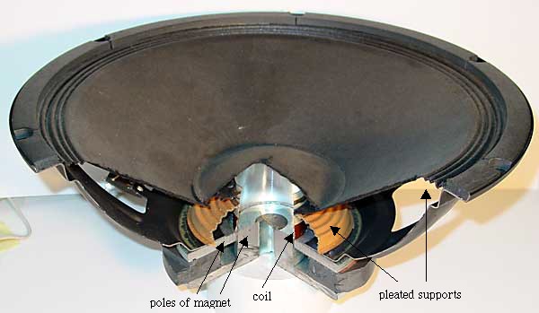
The
coil moves in the field of a permanent magnet, which is usually shaped
to produce maximum force on the coil. The moving coil has no core, so
its mass is small and it may be accelerated quickly, allowing for high
frequency motion. In a loudspeaker, the coil is attached to a light weight
paper cone, which is supported at the inner and outer edges by circular,
pleated paper 'springs'. In the photograph below, the speaker is beyond
the normal upward limit of its travel, so the coil is visible above the
magnet poles.
For low frequency, large wavelength sound, one needs large cones.
The speaker shown below is 380 mm diameter. Speakers designed for
low frequencies are called woofers. They have large mass and are
therefore difficult to accelerate rapidly for high frequency sounds.
In the photograph below, a section has been cut away to show the
internal components.
Tweeters - loudspeakers designed for high frequencies - may be just
speakers of similar design, but with small, low mass cones and coils.
Alternatively, they may use piezoelectric crystals to move the cone.
Speakers are seen to be linear motors with a modest range - perhaps tens of
mm. Similar linear motors, although of course without the paper cone, are often
used to move the reading and writing head radially on a disc drive.
Loudspeakers as microphones
In the picture above, you can see that a cardboard diaphragm (the
loudspeaker cone) is connected to a coil of wire in a magnetic field.
If a soundwave moves the diaphragm, the coil will move in the field,
generating a voltage. This is the principle of a dynamic microphone –
though in most microphones, the diaphragm is rather smaller than the
cone of a loudspeaker. So, a loudspeaker should work as a microphone.
This is a nice project: all you need is a loudspeaker and two wires to
connect it to the input of an oscilloscope or the microphone input of
your computer. Two questions: what do you think the mass of the cone
and coil will do to the frequency response? What about the wavelength
of sounds your use?
Warning: real motors are more complicated
The sketches of motors have been schematics to show the principles.
Please don't be angry if, when you pull a motor apart, it looks more
complicated! For instance, a typical DC motor is
likely to have many separately wound coils to produce smoother torque:
there is always one coil for which the sine term is close to unity.
This is illustrated below for a motor with wound stators (above) and
permanent stators (below).
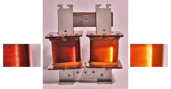
Transformers
The photograph shows a transformer designed for demonstration purposes:
the primary and secondary coils are clearly separated, and may be removed
and replaced by lifting the top section of the core. For our purposes, note
that the coil on the left has fewer coils than that at right (the insets
show close-ups).
The sketch and circuit show a step-up transformer. To make a step-down transformer,
one only has to put the source on the right and the load on the left. (Important
safety note: for a real transformer, you could only 'plug it in backwards'
only after verifying that the voltage rating were appropriate.) So, how does
a transformer work?
The core (shaded) has high magnetic permeability, ie a material that forms
a magnetic field much more easily than free space does, due to the orientation
of atomic dipoles. (In the photograph, the core is laminated soft iron.)
The result is that the field is concentrated inside the core, and almost
no field lines leave the core. If follows that the magnetic fluxes φ through
the primary and secondary are approximately equal, as shown. From Faraday's
law, the emf in each turn, whether in the primary or secondary coil, is −dφ/dt.
If we neglect resistance and other losses in the transformer, the terminal
voltage equals the emf. For the Np turns of the primary, this
gives
Vp = − Np.dφ/dt
.
For the Ns turns of the secondary, this gives
Vs = − Ns.φ/dt
Dividing these equations gives the transformer equation
Vs/Vp = Ns/Np = r.
where r is the turns ratio. What about the current? If we neglect losses in
the transformer (see the section below on efficiency), and if we assume that
the voltage and current have similar phase relationships in the primary and
secondary, then from conservation of energy we may write, in steady state:
Power in = power out, so
VpIp = VsIs, whence
Is/Ip = Np/Ns = 1/r.
So you don't get something for nothing: if you increase the voltage, you decrease
the current by (at least) the same factor. Note that, in the photograph, the
coil with more turns has thinner wire, because it is designed to carry less
current than that with fewer turns.
In some cases, decreasing the current is the aim of the exercise. In power
transmission lines, for example, the power lost in heating the wires due
to their non-zero resistance is proportional to the square of the current.
So it saves a lot of energy to transmit the electrical power from power station
to city at very high voltages so that the currents are only modest.
Finally, and again assuming that the transformer is ideal, let's ask what
the resistor in the secondary circuit 'looks like' to the primary circuit.
In the primary circuit:
Vp = Vs/r and Ip =
Is.r so
Vp/Ip = Vs/r2Is =
R/r2.
R/r2 is called the reflected resistance. Provided that the
frequency is not too high, and provided that there is a load resistance (conditions
usually met in practical transformers), the inductive reactance of the primary
is much smaller than this reflected resistance, so the primary circuit behaves
as though the source were driving a resistor of value R/r2.
Efficiency of transformers
In practice, real transformers are less than 100% efficient.
First, there are resistive losses in the coils (losing power I2.r).
For a given material, the resistance of the coils can be reduced by making
their cross section large. The resistivity can also be made low by using
high purity copper.
Second, there are some eddy current losses in the core. These can be
reduced by laminating the core. Laminations reduce the area of circuits
in the core, and so reduce the Faraday emf, and so the current flowing
in the core, and so the energy thus lost.
Third, there are hysteresis losses in the core. The magentisation and
demagnetisation curves for magnetic materials are often a little different
(hysteresis or history depedence) and this means that the energy required
to magnetise the core (while the current is increasing) is not entirely
recovered during demagnetisation. The difference in energy is lost as heat
in the core.
Finally, the geometric design as well as the material of the core may
be optimised to ensure that the magnetic flux in each coil of the secondary
is nearly the same as that in each coil of the primary.
More about transformers: AC vs DC generators
Transformers only work on AC, which is one of the great advantages of AC. Transformers
allow 240V to be stepped down to convenient levels for digital electronics
(only a few volts) or for other low power applications (typically 12V). Transformers
step the voltage up for transmission, as mentioned above, and down for safe
distribution. Without transformers, the waste of electric power in distribution
networks, already high, would be enormous. It is possible to convert voltages
in DC, but more complicated than with AC. Further, such conversions are often
inefficient and/or expensive. AC has the further advantage that it can be used
on AC motors, which are usually preferable to DC motors for high power applications.


power%20pole.jpg)
steam%20turbine%20used%20to%20collect%20power.jpg)
parts%20of%20electrical%20machine.jpg)
stator%20and%20rotor.jpg)
DC%20motor.jpg)


 Figure 7


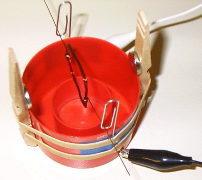
 The
coil moves in the field of a permanent magnet, which is usually shaped
to produce maximum force on the coil. The moving coil has no core, so
its mass is small and it may be accelerated quickly, allowing for high
frequency motion. In a loudspeaker, the coil is attached to a light weight
paper cone, which is supported at the inner and outer edges by circular,
pleated paper 'springs'. In the photograph below, the speaker is beyond
the normal upward limit of its travel, so the coil is visible above the
magnet poles.
For low frequency, large wavelength sound, one needs large cones.
The speaker shown below is 380 mm diameter. Speakers designed for
low frequencies are called woofers. They have large mass and are
therefore difficult to accelerate rapidly for high frequency sounds.
In the photograph below, a section has been cut away to show the
internal components.
The
coil moves in the field of a permanent magnet, which is usually shaped
to produce maximum force on the coil. The moving coil has no core, so
its mass is small and it may be accelerated quickly, allowing for high
frequency motion. In a loudspeaker, the coil is attached to a light weight
paper cone, which is supported at the inner and outer edges by circular,
pleated paper 'springs'. In the photograph below, the speaker is beyond
the normal upward limit of its travel, so the coil is visible above the
magnet poles.
For low frequency, large wavelength sound, one needs large cones.
The speaker shown below is 380 mm diameter. Speakers designed for
low frequencies are called woofers. They have large mass and are
therefore difficult to accelerate rapidly for high frequency sounds.
In the photograph below, a section has been cut away to show the
internal components.