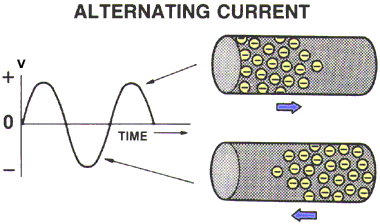
AN ELECTRICAL CIRCUIT
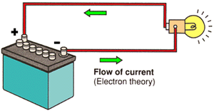
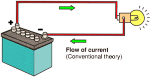
The circuit shown below has a power source, fuse, switch, two lamps and wires connecting each into a loop or circle. When the connection is complete, current flows from the positive terminal of the battery through the wire, the fuse, the switch, another wire, the lamps, a wire and to the negative terminal of the battery. The route along which the electricity flows is called an electrical circuit.

ELECTRICAL CIRCUIT REQUIREMENTS
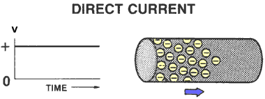
A complete Electrical Circuit is required in order to make electricity practical. Electrons must flow from and return to the power source.
There are three different circuit types, all require the same basic components:
1. Power Source is needed to supply the flow of electrons (electricity).
2. Protection Device prevents damage to the circuit in the event of a short.
3. Load Device converts the electricity into work.
4. Control Device allows the user control to turn the circuit on or off
5. Conductors provide an electrical path to and from the power source.
| BASIC CIRCUIT CONSTRUCTION1. Power Source (Battery, Alternator, Generator, etc.) 2. Protection Device (Fuse, Fusible Link, or Circuit Breaker) 3. Load Device (Lamp, Motor, Winding, Resistor, etc. 4. Control (Switch, Relay, or Transistor) 5. Conductors (A Return Path, Wiring to Ground) |
LOADS
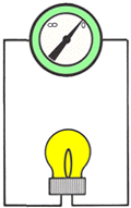
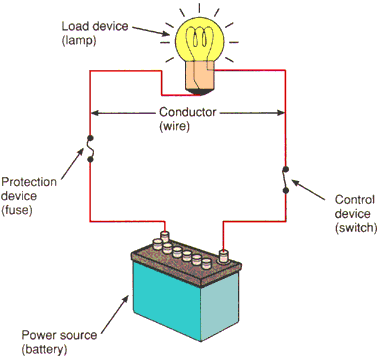
The illustration below has a horn in place of the lamp. Any device such as a lamp, horn, wiper motor, or rear window defogger, that consumes electricity is called a load. In an electrical circuit, all loads are regarded as resistance. Loads use up voltage and control the amount of current flowing in a circuit. Loads with high resistance cause less current to flow while those with lower resistance allow high current rates to flow.
AUTOMOTIVE ELECTRICAL CIRCUITS
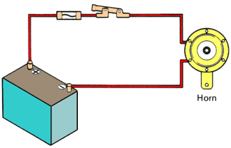
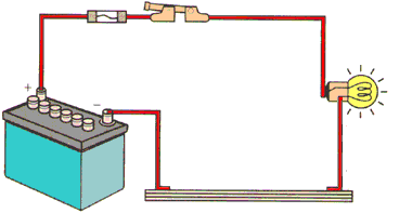
In an automotive electrical circuit, one end of the wire from each load returning to the battery is connected to the vehicle body or frame. Therefore, the vehicle body or frame itself functions as a conductor, allowing current to flow though the body or frame and back to the battery. The body or frame is then referred to as the body ground (or earth) of the circuit (meaning that part of the circuit that returns the current to the battery).
WHAT IS OHM'S LAW?
A simple relationship exists between voltage, current, and resistance in electrical circuits. Understanding this relationship is important for fast, accurate electrical problem diagnosis and repair.
OHM'S LAW
Ohm's Law says: The current in a circuit is directly proportional to the applied voltage and inversely proportional to the amount of resistance. This means that if the voltage goes up, the current flow will go up, and vice versa. Also, as the resistance goes up, the current goes down, and vice versa. Ohm's Law can be put to good use in electrical troubleshooting. But calculating precise values for voltage, current, and resistance is not always practical ... nor, really needed. A more practical, less time-consuming use of Ohm's Law would be to simply apply the concepts involved:
SOURCE VOLTAGE is not affected by either current or resistance. It is either too low, normal, or too high. If it is too low, current will be low. If it is normal, current will be high if resistance is low, or current will be low if resistance is high. If voltage is too high, current will be high.
CURRENT is affected by either voltage or resistance. If the voltage is high or the resistance is low, current will be high. If the voltage is low or the resistance is high, current will be low.
RESISTANCE is not affected by either voltage or current. It is either too low, okay, or too high. If resistance is too low, current will be high at any voltage. If resistance is too high, current will be low if voltage is okay.
NOTE: When the voltage stays the same, such as in an Automotive Circuit... current goes up as resistance goes down, and current goes down as resistance goes up. Bypassed devices reduce resistance, causing high current. Loose connections increase resistance, causing low current.
OHM'S LAW FORMULA
When voltage is applied to an electrical circuit, current flows in the circuit. The following special relationship exists among the voltage, current and resistance within the circuit: the size of the current that flows in a circuit varies in proportion to the voltage which is applied to the circuit, and in inverse proportion to the resistance through which it must pass. This relationship is called Ohm's law, and can be expressed as follows:
E = I R
Voltage = Current x Resistance
| E Voltage applied to the circuit, in volts (V)I Current flowing in the circuit, in amperes (A) R Resistance in the circuit, in ohms |
In practical terms "V = I x R" which means
"Voltage = Current x Resistance".
1 volt will push one amp through 1 ohm of resistance.
NOTE: E = IR, V=AR, or V=IR are all variations of the same formula. How you learned Ohm's law will determine which one you will use. Personal preference is the only difference; anyone will get you the correct answer.
OHM'S LAW SYMBOL SHORTCUT
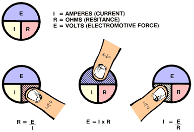
Mathematical formulas can be difficult for many who don't use them regularly. Most people can remember a picture easier than a mathematical formula. By using the Ohms law symbol below, anyone can remember the correct formula to use. By knowing any two values you can figure out the third. Simply put your finger over the portion of the symbol you are trying to figure out and you have your formula.
APPLICATIONS OF OHM'S LAW
As an application of Ohm's law, any voltage V, current I or resistance R in an electrical circuit can be determined without actually measuring it if the two others values are known.
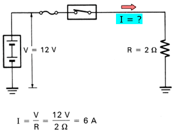
This law can be used to determine the amount of current I flowing in the circuit when voltage V is applied to resistance R. As stated previously, Ohm's law is:

Current = Voltage / Resistance.
In the following circuit, assume that resistance R is 2 and voltage V that is applied to it is 12 V. Then, current I flowing in the circuit can be determined as follows:
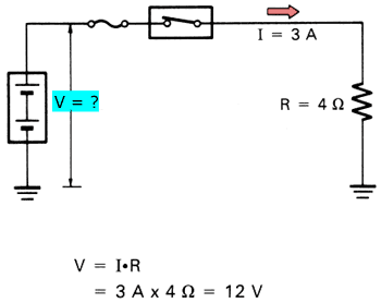
This law can also be used to determine the voltage V that is needed to permit current I to pass through resistance R: V = I x R (Voltage= Current x Resistance).
In the following circuit, assume that resistance R is 4 ohms. The voltage V that is necessary to permit a current I of 3 A to pass through the resistance can be determined as follows:
Still another application of the law can be used to determine the resistance R when the voltage V which is applied to the circuit and current I flowing in the circuit are already known:

In the following circuit, assume that a voltage V of 12 V is applied to the circuit and current I of 4 A flows in it. Then, the resistance value R of the resistance or load can be determined as follows:

TYPES OF CIRCUITS
Individual electrical circuits normally combine one or more resistance or load devices. The design of the automotive electrical circuit will determine which type of circuit is used. There are three basic types of circuits:
Series Circuit
Parallel Circuit
Series-Parallel Circuit
SERIES CIRCUITS
A series circuit is the simplest circuit. The conductors, control and protection devices, loads, and power source are connected with only one path to ground for current flow. The resistance of each device can be different. The same amount of current will flow through each. The voltage across each will be different. If the path is broken, no current flows and no part of the circuit works. Christmas tree lights are a good example; when one light goes out the entire string stops working.

SERIES CIRCUITS
A Series Circuit has only one path to ground, so electrons must go through each component to get back to ground. All loads are placed in series.
Therefore:
1. An open in the circuit will disable the entire circuit.
2. The voltage divides (shared) between the loads.
3. The current flow is the same throughout the circuit.
4. The resistance of each load can be different.

SERIES CIRCUIT CALCULATIONS
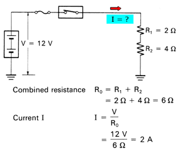
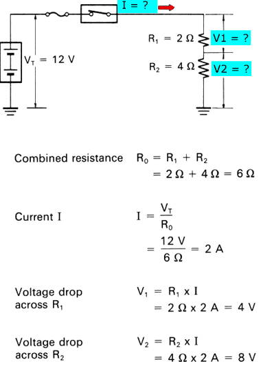
If, for example, two or more lamps (resistances R1 and R2, etc.) are connected in a circuit as follows, there is only one route that the current can take. This type of connection is called a series connection. The value of current I is always the same at any point in a series circuit.
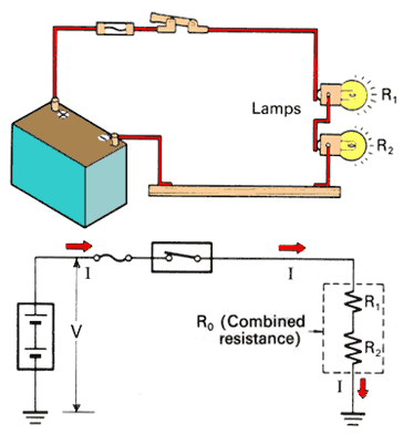
The combined resistance RO in this circuit is equal to the sum of individual resistance R1 and R2. In other words: The total resistance(RO) is equal to the sum of all resistances (R1 + R2 + R3 + .......)

Therefore, the strength of current (I) flowing in the circuit can be found as follows:

Resistance R0 (a combination of resistances R1 and R2, which are connected in series in the circuit as illustrated) and current I flowing in this circuit can be determined as follows:
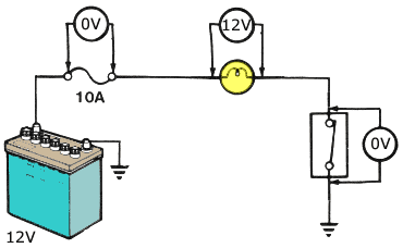
VOLTAGE DROP
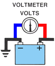
A voltage drop is the amount of voltage or electrical pressure that is used or given up as electrons pass through a resistance (load). All voltage will be used up in the circuit. The sum of the voltage drops will equal source voltage. A voltage drop measurement is done by measuring the voltage before entering the load and the voltage as it leaves the load. The difference between these two voltage readings is the voltage drop.
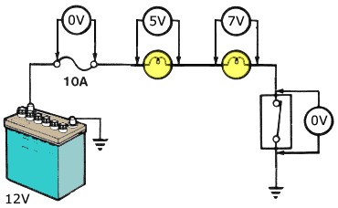
VOLTAGE DROP TOTAL
When more than one load exists in a circuit, the voltage divides and will be shared among the loads. The sum of the voltage drops equal source voltage. The higher the resistance the higher the voltage drop. Depending on the resistance, each load will have a different voltage drop.
0V + 5V + 7V + 0V = 12V
VOLTAGE DROP CALCULATION
When current flows in a circuit, the presence of a resistance in that circuit will cause the voltage to fall or drop as it passes through the resistance. The resultant difference in the voltage on each side of the resistance is called a voltage drop. When current (I) flows in the following circuit, voltage drops V1 and V2 across resistances R1 and R2 can be determined as follows from Ohm's law. (The value of current I is the same for both R1 and R2 since they are connected in series.)
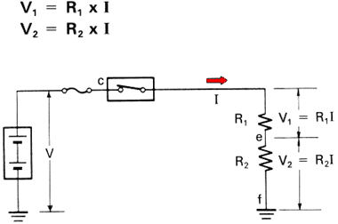
The sum of the voltage drops across all resistances is equal to the voltage of the power source (VT):
The voltage drop across resistances R1 and R2 in the following circuit can be determined as follows:
PARALLEL CIRCUIT
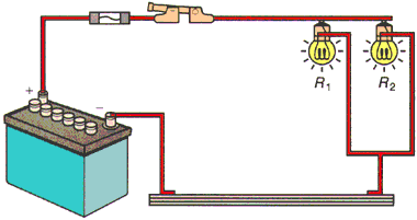
A parallel circuit has more than one path for current flow. The same voltage is applied across each branch. If the load resistance in each branch is the same, the current in each branch will be the same. If the load resistance in each branch is different, the current in each branch will be different. If one branch is broken, current will continue flowing to the other branches.
PARALLEL CIRCUITS
A Parallel Circuit has multiple paths or branches to ground. Therefore:
1. In the event of an open in the circuit in one of the branches, current will continue to flow through the remaining.
2. Each branch receives source voltage.
3. Current flow through each branch can be different.
4. The resistance of each branch can be different.

PARALLEL CIRCUIT
In parallel connection, two or more resistances (R1, R2, etc.) are connected in a circuit as follows, with one end of each resistance connected to the high (positive) side of the circuit, and one end connected to the low (negative) side. Full battery voltage is applied to all resistances within a circuit having a parallel connection.

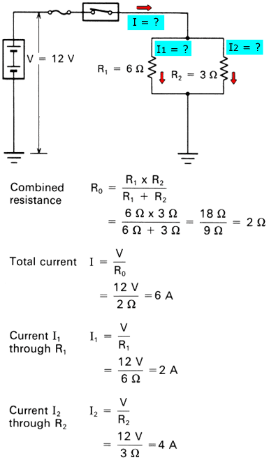
Resistance R0 (a combination of resistances R1 and R2) in a parallel connection can be determined as follows:

From the above, the total current I flowing in this circuit can be determined from Ohm's law as follows:
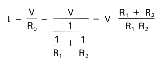
The total current I is also equal to the sum of currents I1 and I2 flowing through individual resistances R1 and R2

Since battery voltage V is applied equally to all resistances, the strength of currents I1 and I2 can be determined from Ohm's law as follows:

Resistance RO (a combination of resistances R1 and R2, which are connected in parallel in the circuit as shown below), the total current I flowing in the circuit, and currents I1 andI2 flowing through resistances R1 and R2, can be determined respectively as follows:
SERIES PARALLEL CIRCUIT
A series-parallel circuit has some components in series and others in parallel. The power source and control or protection devices are usually in series; the loads are usually in parallel. The same current flows in the series portion, different currents in the parallel portion. The same voltage is applied to parallel devices, different voltages to series devices. If the series portion is broken, current stops flowing in the entire circuit. If a parallel branch is broken, current continues flowing in the series portion and the remaining branches.
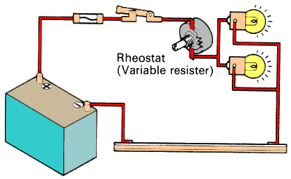
SERIES-PARALLEL CIRCUIT
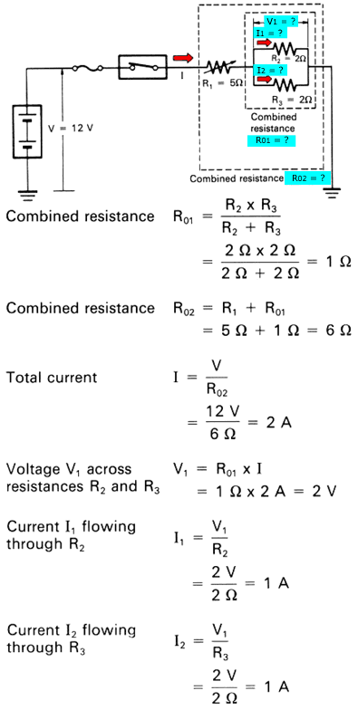
A resistance and lamps may be connected in a circuit as illustrated below. This type of connecting method is called series-parallel connection, and is a combination of series and parallel connections. The interior dash board lights are a good example. By adjusting the rheostat, you can increase or decrease the brilliance of the lights.
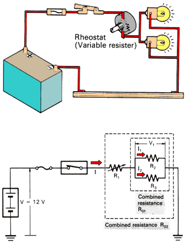
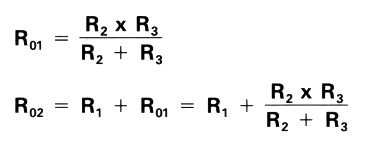
The combined resistance R02 in this series-parallel connection can be determined in the following order:
a. Determine combined resistance R01, which is a combination of resistances R2 and R3 connected in parallel.
b. Then, determine resistance R02, which is a combination of resistance R1 and combined resistance R01 connected in series.
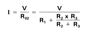
Total current I flowing in the circuit can be determined from Ohm's law as follows:
The voltage applied to R2 and R3 can be found by the following formula:

Currents I1, I2 and I flowing through resistances R1, R2 and R3 in the series-parallel connection, as shown below, can be determined as follows:
