Related

Saturday, November 1, 2014

How to Make a Simple Electric Motor

Energy comes in many forms. Electric energy can be converted into useful work, or mechanical energy, by machines called electric motors. Electric motors work due to electromagnetic interactions: the interaction of current (the flow of electrons) and a magnetic field.

Problem

Find out how to make a simple electric motor.

Materials

  • D battery
  • Insulated 22G wire
  • 2 large-eyed, long, metal sewing needles (the eyes must be large enough to fit the wire through)
  • Modeling clay
  • Electrical tape
  • Hobby knife
  • Small circular magnet
  • Thin marker
Electric Motor Materials

Procedure

  1. Starting in the center of the wire, wrap the wire tightly and neatly around the marker 30 times.
  2. Slide the coil you made off of the marker.
  3. Wrap each loose end of the wire around the coil a few times to hold it together, then point the wires away from the loop, as shown:
Electric Motor Armature
What is this? What is its purpose?
  1. Ask an adult to use the hobby knife to help you remove the top-half of the wire insulation on each free end of the coil. The exposed wire should be facing the same direction on both sides. Why do you think half of the wire needs to remain insulated?
Electric Motor Removing Insulation
  1. Thread each loose end of the wire coil through the large eye of a needle. Try to keep the coil as straight as possible without bending the wire ends.
Electric Motor Needles
  1. Lay the D battery sideways on a flat surface.
  2. Stick some modeling clay on either side of the battery so it does not roll away.
  3. Take 2 small balls of modeling clay and cover the sharp ends of the needle.
  4. Place the needles upright next to the terminals of each battery so that the side of each needle touches one terminal of the battery.
Electric Motor with Clay
  1. Use electrical tape to secure the needles to the ends of the battery. Your coil should be hanging above the battery.
  2. Tape the small magnet to the side of the battery so that it is centered underneath the coil.
Completed Electric Motor
  1. Give your coil a spin. What happens? What happens when you spin the coil in the other direction? What would happen with a bigger magnet? A bigger battery? Thicker wire?

Results

The motor will continue to spin when pushed in the right direction. The motor will not spin when the initial push is in the opposite direction.

Why?

The metal, needles, and wire created a closed loop circuit that can carry current. Current flows from the negative terminal of the battery, through the circuit, and to the positive terminal of the battery. Current in a closed loop also creates its own magnetic field, which you can determine by the “Right Hand Rule.” Making a “thumbs up” sign with your right hand, the thumb points in the direction of the current, and the curve of the fingers show which way the magnetic field is oriented.
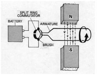
In our case, current travels through the coil you created, which is called the armature of the motor. This current induces a magnetic field in the coil, which helps explain why the coil spins.
Magnets have two poles, north and south. North-south interactions stick together, and north-north and south-south interactions repel each other. Because the magnetic field created by the current in the wire is not perpendicular to the magnet taped to the battery, at least some part of the wire’s magnetic field will repel and cause the coil to continue to spin.
So why did we need to remove the insulation from only one side of each wire? We need a way to periodically break the circuit so that it pulses on and off in time with the rotation of the coil. Otherwise, the copper coil’s magnetic field would align with the magnet’s magnetic field and stop moving because both fields would attract each other. The way we set up our engine makes it so that whenever current is moving through the coil (giving it a magnetic field), the coil is in a good position to be repelled by the stationary magnet’s magnetic field. Whenever the coil isn’t being actively repelled (during those split second intervals where the circuit is switched off), momentum carries it around until it’s in the right position to complete the circuit, induce a new magnetic field, and be repelled by the stationary magnet again.
Once moving, the coil can continue to spin until the battery is dead. The reason that the magnet only spins in one direction is because spinning in the wrong direction will not cause the magnetic fields to repel each other, but attract.

Electric motor

       An electric motor is a device used to convert electrical energy to mechanical energy. Electric motors are extremely important in modern-day life. They are used in vacuum cleaners, dishwashers, computer printers, fax machines, video cassette recorders, machine tools, printing presses, automobiles, subway systems, sewage treatment plants, and water pumping stations, to mention only a few applications.

Principle of operation

The basic principle on which motors operate is Ampere's law. This law states that a wire carrying an electric current produces a magnetic field around itself. Imagine that current is flowing through

A figure of an electric motor. (Reproduced by permission of The Gale Group.)
A figure of an electric motor. 

the wire loop shown in the figure below. The presence of that current creates a magnetic field around the wire. Since the loop itself has become a magnet, one side of it will be attracted to the north (N) pole of the surrounding magnet and the other side will be attracted to the south (S) pole of the magnet. The loop will begin to rotate, as shown by the arrow marked F.

AC motors. 
What happens next depends on the kind of electric current used to run the motor, direct (DC) or alternating (AC) current. With AC current, the direction in which the current flows changes back and forth rapidly and at a regular rate. In the United States, the rate of change is 60 times per second, or 60 hertz (the unit of frequency).

In an AC motor, then, the current flows first in one direction through the wire loop and then reverses itself about 1/60 second later. This change of direction means that the magnetic field produced around the loop also changes once every 1/60 second. At one instant, one part of the loop is attracted by the north pole of the magnet, and at the next instant, it is attracted by the south pole of the magnet.
But this shifting of the magnetic field is necessary to keep the motor operating. When the current is flowing in one direction, the right hand side of the coil might become the south pole of the loop magnet. It would be repelled by the south pole of the outside magnet and attracted by the north pole of the outside magnet. The wire loop would be twisted around until the right side of the loop had completed half a revolution and was next to the north pole of the outside magnet.

If nothing further happened, the loop would come to a stop, since two opposite magnetic poles—one from the outside magnet and one from the wire loop—would be adjacent to (located next to) each other. And unlike magnetic poles attract each other. But something further does happen. The current changes direction, and so does the magnetic field around the wire loop. The side of the loop that was previously attracted to the north pole is now attracted to the south pole, and vice versa. Therefore, the loop receives another "kick," twisting it around on its axis in response to the new forces of magnetic attraction and repulsion.

Thus, as long as the current continues to change direction, the wire loop is forced to spin around on its axis. This spinning motion can be used to operate any one of the electrical appliances mentioned above.

DC motors. 
When electric motors were first invented, AC current had not yet been discovered. So the earliest motors all operated on DC current, such as the current provided by a battery.

Capacitor

A capacitor is a device for storing electrical energy. Capacitors are used in a wide variety of applications today. Engineers use large banks of capacitors, for example, to test the performance of an electrical circuit when struck by a bolt of lighting. The energy released by these large capacitors is similar to the lightning bolt. On another scale, a camera flash works by storing energy in a capacitor and then releasing it to cause a quick bright flash of light. On the smallest scale, capacitors are used in computer systems. A charged capacitor represents the number 1 and an uncharged capacitor a 0 in the binary number system used by computers.

How a capacitor stores energy A capacitor consists of two electrical conductors that are not in contact. The conductors are usually separated by a layer of insulating material known as a dielectric. Since air is a dielectric, an additional insulating material may not have to be added to the capacitor.
Think of a capacitor as consisting of two copper plates separated by 1 centimeter of air. Then imagine that electrical charge (that is, electrons) are pumped into one of the plates. That plate becomes negatively charged because of the excess number of electrons it contains. The negative charge on the first copper plate then induces (creates) a positive charge on the second plate.

As electrons are added to the first plate, one might expect a current to flow from that plate to the second plate. But the presence of the dielectric prevents any flow of electrical current. Instead, as more electrons are added to the first plate, it accumulates more and more energy. Adding electrons increases energy because each electron added to the plate has to overcome repulsion from other electrons already there. The tenth electron added has to bring with it more energy to add to the plate than did the fifth electron. And the one-hundredth electron will have to bring with it even more energy. As a result, as long as current flows into the first plate, it stores up more and more electrical energy.

Capacitors release the energy stored within them when the two plates are connected with each other. For example, just closing an electric switch between the two plates releases the energy stored in the first plate. That energy rushes through the circuit, providing a burst of energy.
The primary difference between a DC motor and an AC motor is finding a way to change the direction of current flow. In direct current, electric current always moves in the same direction. That means that the wire loop in the motor will stop turning after the first half revolution. Because the current is always flowing in the same direction, the resulting magnetic field always points in the same direction.

To solve this problem, the wire coming from the DC power source is attached to a metal ring cut in half, as shown in the figure. The ring is called a split-ring commutator. At the first moment the motor is turned on, current flows out of the battery, through the wire, and into one side of the commutator. The current then flows into the wire loop, producing a magnetic field.

Once the loop begins to rotate, however, it carries the commutator with it. After a half turn, the ring reaches the empty space in the two halves and then moves on to the second half of the commutator. At that point, then, current begins to flow into the opposite side of the loop, producing the same effect achieved with AC current. Current flows backward through the loop, the magnetic field is reversed, and the loop continues to rotate.